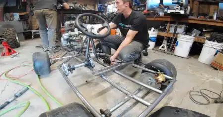
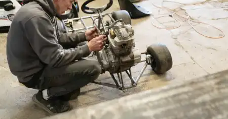
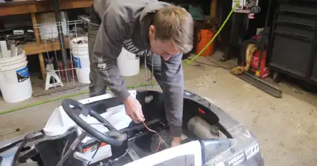
Building power wheels Go Kart could be a challenging task, but actually, it is not. So if you do not do it before, no worry, our step-by-step guidelines considering Power Wheels Go Kart Conversion could be a great help for you. To learn more, stay tuned with us.
Steps by Step Build Process: How to Power Wheels Go Kart Conversion
1st Step- Chain Setup
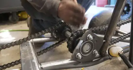
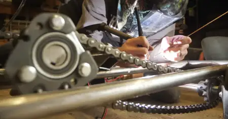
The main thing is the proper alignment with the rear axle and with the engines to ensure that chains are in excellent alignment, remain straight, and do not wear weirdly. Also you need to ensure that chains run off the sprockets or anything like that.
So you need to use the real axle to keep it straight as I do for the whole build and try to measure that on both sides and ensure it from square to the axle and make sure you have to take it in a place where your chains are decently tight.
You also need to ensure that to get them in proper length, because it matters. It is also necessary to keep them loose enough that they avoid yanking on everything. Ensure the side should not rub together when getting them on and tight enough while putting a tensioner on both sides.
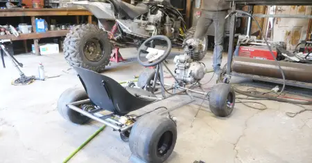
I made this for the front seat, installed the bracket to elevate the front a little bit, leant the seatback to make it more comfortable for the position. But if you are using a square tube to build the whole frame. It will be easier to do everything that we have done.
You can use the round tube because it is nice to bend, but a square tube is better when you are not turning.
2nd Step- Clutch Setup
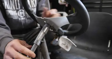
Next, I will work on the clutch setup, so it involved more, but I did not cover it more because it depends on the motor and clutch setup. Usually, handlebar clutch you can use, I also used that, and it worked. So all that I did was prepare a little bracket, mount it to it, and then cut the handlebar tip. Then I took a piece of Aluminum angle iron and rounded it, gave it a slight shape, and it nicely worked.
But it does not matter; the only important thing to remember is how sharp this angle is when you are going at your whole turn, but it isn't easy. The second thing is if you have the body in, as I started offlining on top. It would not work. It would have had to cut most of the windshield out, which is a no-go for me, and the next thing is a cable; it would be in a better position.
While positioning, keep your body in mind and how sharp the angle on the clutch is. If it is too sharp in the corner, it might be harder to pull the lever, like pulling the lever in the right. So make sure while you pull, it does not touch anything.
3rd step - Brake Setup
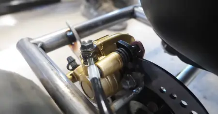
I will start with mounting the caliper, and after that, I will work on the cable and foot pedal. If the cable is hydraulic, then we need to run a cable from here up to the front, so I will install it where it belongs. Then on the disc back there, I will do some cable up to a pedal up in that area, and next, I will mount that with a master cylinder somewhere near this area. All other parts will be in link with the description.
From this area, power sports will go, so you should check and see what you need more. I will end that by doing a little cab for the brake caliper mount so that I will take the pads out of the caliper; that way, I can easily slide the bracket out, and then I will mark the rotor in the same way as I used to mark that before.
I know where the caliper should be, and I can cut that output of the caliper back together. But make sure it is going to fit around the rest of the body of the caliper. Once it has gone fit, I can cut this out of metal and make the actual mount.
4th Step- Frame Setup
Now I take a bracket that is already prepared; you can also take it from the market, and I will weld it to the frame. First, I am drilling a couple of holes into the mount of the caliper; once I get this fit here, then I shall put another little support here for it, and I will be able to work on its mounting.
After that, I will link it with a pedal; you will also need sprockets to quickly get from a local store and at a meager price. You can also use stock from the motorcycle chain, but it will be easier if you get 50 number sprockets from the local store, it will be thinner and robust. In addition, you can efficiently work with them.
These will be like the standard machine chain, and you can lose them on your front sprockets that are okay. All right, I got this bracket here; I do not want to leave a gap due to the resting caliper and bracket. So I will put a mark between these two.
When I take it out, I will mark where the holes are, and then I will move the center notch over just barely, but it will be helpful for me to line it up. I cannot guess about the caliper position until that time because it is loosely fit right now.
So I will mark a little sharpening there, and then I shall go ahead and mark holes in the center when I do punching in the center. But I will ensure that it should have a slight gap between the bracket and caliper when done.
5th step- Make Push Rod for Brake
We need a little thin piece of steel to make a push rod for the brake; you can also use aluminum rods. I will use these rods to make a pull for the brake, and then I will give them a shape on the outside of the pebble and put a little plate on it.
6th Step – Make Brake Pedal
Now move forward for the Brake pedal; the first step is to come up with a pedal you can get from the store, or if you have an older one, it can be used. The next thing we need is a bearing, now take the piece of tube and weld the tube with the pedal.
When assembling one more thing, mount that from the side from where we will add spring. Then, after doing all that, we will attach the master cylinder and the rod back. That is the pedal; it will be great.
7th Step- Master Brake Cylinder Setup
The next step is to install the master brake cylinder to make the connection between. What I needed for this I need too close to the body just for aesthetics. So push the rod gently for the pedal; it will be on an angle, but it is okay.
Now use the same tube as I use for the bearing, cut a piece there, and then weld a nut. It is unique, and you always need to screw the bolt in so when welding this. But do not mess up these threads or get any berries in there. It is pretty easy; when the part is welded with the frame and then with the bolt, the bolt will come, and it will be removed.
Brakes have been done; you know it was just the shaft that you can go directly on with the bolt through there, and you will be able to do a tiny section of the outside of a tie rod. Then, after that, you will need to weld the tie rod to the shaft to make it easier.
8th Step- Finish up Wiring
Finishing up the wiring, borrowing this we will put it back do not worry, you know there is Cinderella's fuel tank so we should hide it. It will also be supportive to even the weight, and we will also be able to put the battery; you can also hide it under the seat, whichever you like.
I was saying that I am making a hard push to try to get this running today, so I will zip-tied this fuel tank on the back and install the fuel pump that is pretty simple once you have wired it.
Power wire will go to the ignition key and then ground onto the body; it will work excellent with the carburetor and the air filter, so we will try to start it up. Uh, that sounds healthy without a header.
That’s it. Usually the Go Kart is powered by a gasoline engine (4-stroke), while you convert it, you need to know the basics of the power wheels gas engine conversion process. Hope, the above mentioned process could give you a relief from any technical hassle regarding the conversion process.
Final Thoughts
Power Wheels Go Kart Conversion may be difficult for you, but it isn't an impossible mission. All these steps mentioned above are more straightforward but you need to be careful while performing gas powered power wheels Go Kart Conversion. We hope, now you can make your power wheels Go kart yourself. Power Wheels Go Kart Conversion may be difficult for you, but it isn't an impossible mission.
Recommended To Read Articles:

